E24: Adjusting throttle valves on an M635CSi (M88)
This article describes how to check and eventually adjust the throttle valves on an M635CSi. This is by no means a straightforward procedure, requiring more than a weekend's hard work and at least some special tools, like a sliding vernier caliper (measuring accuracy of tenths of millimeters or better), a dial gauge able to measure disposition with an accuracy of hundredths of millimeters plus mounting material, and a vacuum synchrotester (like Carbtune). For an overview of special tools and alternatives, check my other post:
BMW special tools
This procedure is not un-doable, but if your engine is running fine in idle, and responding nicely to the throttle, it's probably enough to just clean and lubricate the moving parts on the throttle bodies (shaft, bearings, pushing rods).
 Abbreviations:
- TB Throttle Body
- ICV Idle Control Valve
1) REMOVE ACCUMULATOR
Start off by removing the Accumulator, as described in Overhauling the accumlator on an M635CSI

2) REMOVE FUEL INJECTOR RAIL
NOTE:
Steps 2, 3 and 4 are only required in case you want to overhaul the TBs, for example to replace the needle bearings, or when the springs that close the valves are in need of maintenance, or when you suspect that the basic setting of the clamp to the axle that operates the valves needs re-adjustment. If you only want to adjust the valves to their basic setting and synchronize the 3 TBs, they can remain installed and you can proceed to step 5.
Remove the (blue) connector to the cold-start injector by prying out the metal clip with a small screwdriver. Carefully pull off the plastic bar that holds the 6 connectors to the injectors. This can best be done by starting on one end of the bar, not from the middle!

Disconnect the hoses to the cold start injector and from the pressure regulator by loosening the clamps. This can best be done on the side of the fuel rail as in picture below. Keep some paper towel at hand, because fuel will spill. Use short pieces of hose or rubber caps to close the 2 outlets on the rail to prevent further fuel dripping.
Use a 13mm socket to remove the 2 bolts that fasten the fuel rail to the engine.

Now the complete fuel rail including injectors can be lifted from the throttle bodies. The injectors are only kept in place by the O-rings, but it does take some strength to pull them out. It's best to wriggle the fuel rail until an injector on one side pops out, and then the other five will follow soon...

If you will overhaul your injectors, you can read how to remove them from the rail in my other post
Remove injectors
If not, you can manoeuvre the rail out of the way so that it's not hampering the rest of the activities.

3) KNOCK OUT FIXING PINS FROM SHAFT
This section describes the removal of the pins that fix the levers to the shaft that links the 3 TBs. Again, this can also be done at a later stage -after removal of the TBs- or not at all, depending on what you want to overhaul on your throttle bodies. If you need to separate the 3 TBs, for example to replace the needle bearings, the shaft must be removed and this is only possible with at least the 2 fixing pins removed that sit at the shaft's outer ends, fixing levers #2 and #6 in the picture below.

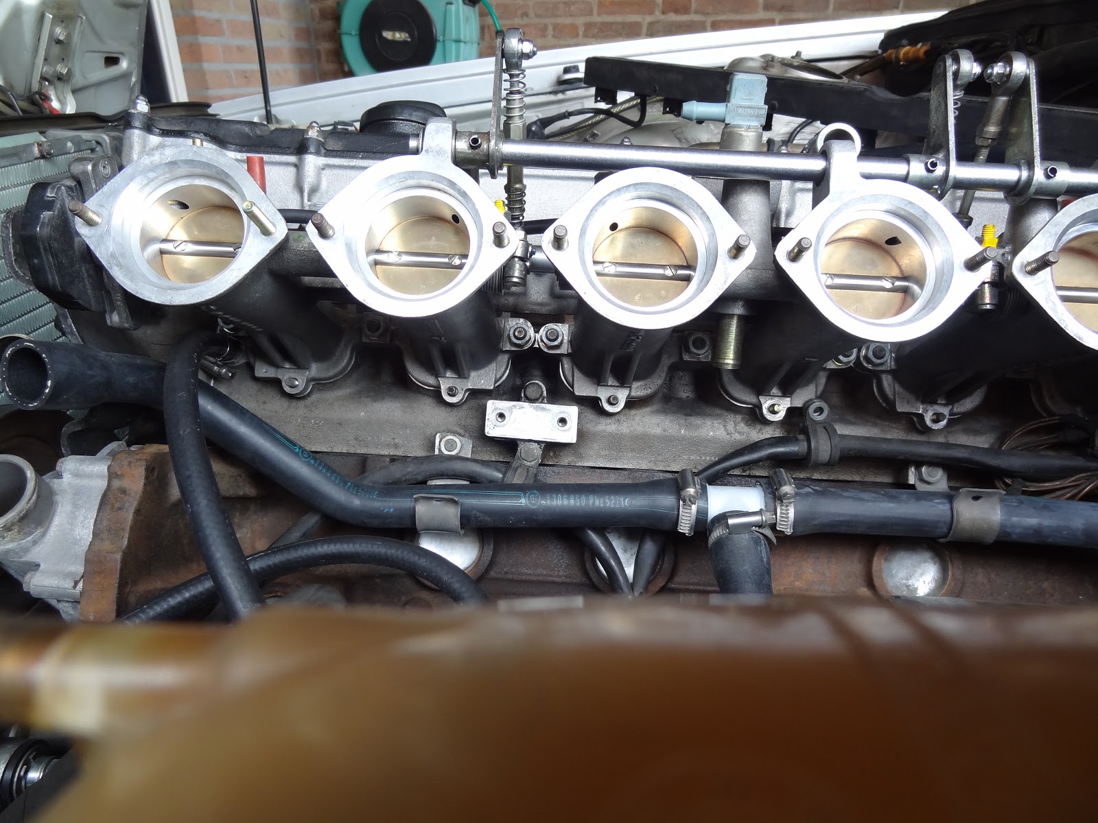
Since removing the pins requires a substantial amount of force, it's probably easier when the throttle bodies are still attached to the engine head. As can be seen in the following picture, the gap between the two push rods is too small to be able to remove the rods without removing the fixing pins first. With the fixing pins removed, the levers can be rotated just enough to provide the clearance needed for the removal of the push rods.

The pin -actually a tube with a slit- is made of very hard steel, therefore it cannot be drilled out. It can be driven out with a hammer and a 5mm drill.

With the fixing pins removed, the levers can be slightly rotated, giving enough clearance to remove the push rods.

4) REMOVE THROTTLE BODIES
The middle TB is connected to the Idle Control Valve with 2 inlets: one before the butterfly valves (bottomside of the TB) and one behind the butterfly valves (topside of the TB). Before the TB can be removed, the hoses to these inlets must be disconnected.
NOTE:
Actually the name ICV is misplaced. This is not a closed loop control system, but rather a slide that depending on motor temperature allows additional air to bypass the intake valves. Therefore the part is usually referred to as Additional Air Slide

It's somewhat awkward to disconnect the hose from the topside of the TB, therefore this one is best disconnected at the ICV.

Alternatively, the ICV can remain connected to the TB, in case it is removed together with the TB. The other hose can be disconnected from the bottomside of the TB.

Each TB is mounted to the engine head with 6 hexnuts. Note that the nut on the right TB also connects the wiring loom to the car's mass.

Unscrew all the hexnuts with a 13mm socket. These nuts have a tendency of getting lost in some corner of the block, so precaution is required! Store the nuts and washers in a safe place.

Carefully remove the 3 TBs.

Once removed they are only held together by the linking shaft. Make sure not to twist the TBs, since it will strain or damage the needle bearings. Store the TBs in a safe place.
If you will overhaul the TBs, have a look at my other post:
Overhauling Throttle Bodies

5) SYNCHRONIZE VALVE OPERATION
This step assumes that you have overhauled the TBs as described in steps 2,3,4 or if you continued here after step 1. In any case the TBs are mounted on the engine head, and the basic setting of the clamps, idle-stop screws and push rods has been done as described in my other post. The push rod for cilinders #5 and #6 (closest to the firewall) has been set to 97,5 mm as indicated in the picture below. The 2 push rods for cilinders #1~4 have been set to 100 mm.
The theory behind this difference, is that the valves of cilinders #5,6 (operated by the shortest push rod) are closed at start of the adjustment procedure, whereas the valves of cilinders #1~4 are slightly opened. A dial gauge with preload is used to measure the disposition (or rather movement) of the push rod to cilinders #5,6. When for example the push rod operation cilinders #3,4 is adjusted (i.e. shortened), first the valves will gradually close until the idle-stop screw is hit. Further adjusting would pull the lever on the linking shaft, effectively causing the valves of cilinders #5,6 to start opening. This movement will be reflected on the dial gauge.
In short: as soon as the valves for cilinders #5,6 start to open -indicated by rotation of the dial gauge needle- the synchronization is complete.


Mount special tool 00 2 500 to one of the stay bolts of the throttle body belonging to cilinders #5,6.
For alternatives to the special tools, see my post:
BMW special tools
Mount special tool 00 2 510 (i.e. the dial gauge) onto the holder such that the feeler tip of the gauge is pressing against the lever connected to the push rod of cilinders #5,6. The dial gauge must be preloaded, e.g. in the picture below the feeler tip has been pressed 2,24 mm, but this can be any other value. I'd recommend at least 1 mm. The preload is needed to allow the needle to move in the direction of a smaller disposition, which occurs at the moment that the lever is moving downwards.


Now start adjusting the push rod belonging to cilinders #3,4 by rotating the adjustment screw counter-clockwise with a 10 mm wrench. When the needle starts moving (also counter-clockwise), the valves of cilinders #3,4 will be in their idle position, the clamp resting against the idle-stop screw. The procedure must then be repeated for the push rod of cilinders #1,2. See also the following clip:
Once the synchronization has been done, the valve clearances at full load need to be checked and possibly adjusted. Press the throttle lever against the full load stop screw.

Use a vernier caliper to measure the valve opening distances A and B of all 6 cilinders. When the basic setting and synchronization have been done perfectly, the measured distances should be the same for all cilinders, with design specification for:
A = 21,7 mm
B = 22,7 mm

Calculate the average over all 6 cilinders, and if necessary adjust the full load stop screw such that the average moves in the direction of the design specification.
6) ADJUST CO / VACUUM
This step is by no means straightforward, since there are multiple screws that can be adjusted, and they influence each other. Therefore it may require multiple iterations before the optimal setting is achieved. High level, the approach is as follows:
- Adjust the idle speed by means of the central Oxygen screw
- Adjust the CO level with the control screw on the AFM
- Adjust the 6 CO screws on the throttle bodies to synchronize the vacuum pressure
BMW special tools
This procedure is not un-doable, but if your engine is running fine in idle, and responding nicely to the throttle, it's probably enough to just clean and lubricate the moving parts on the throttle bodies (shaft, bearings, pushing rods).

- TB Throttle Body
- ICV Idle Control Valve
1) REMOVE ACCUMULATOR
Start off by removing the Accumulator, as described in Overhauling the accumlator on an M635CSI

2) REMOVE FUEL INJECTOR RAIL
NOTE:
Steps 2, 3 and 4 are only required in case you want to overhaul the TBs, for example to replace the needle bearings, or when the springs that close the valves are in need of maintenance, or when you suspect that the basic setting of the clamp to the axle that operates the valves needs re-adjustment. If you only want to adjust the valves to their basic setting and synchronize the 3 TBs, they can remain installed and you can proceed to step 5.
Remove the (blue) connector to the cold-start injector by prying out the metal clip with a small screwdriver. Carefully pull off the plastic bar that holds the 6 connectors to the injectors. This can best be done by starting on one end of the bar, not from the middle!

Disconnect the hoses to the cold start injector and from the pressure regulator by loosening the clamps. This can best be done on the side of the fuel rail as in picture below. Keep some paper towel at hand, because fuel will spill. Use short pieces of hose or rubber caps to close the 2 outlets on the rail to prevent further fuel dripping.
Use a 13mm socket to remove the 2 bolts that fasten the fuel rail to the engine.

Now the complete fuel rail including injectors can be lifted from the throttle bodies. The injectors are only kept in place by the O-rings, but it does take some strength to pull them out. It's best to wriggle the fuel rail until an injector on one side pops out, and then the other five will follow soon...

If you will overhaul your injectors, you can read how to remove them from the rail in my other post
Remove injectors
If not, you can manoeuvre the rail out of the way so that it's not hampering the rest of the activities.

3) KNOCK OUT FIXING PINS FROM SHAFT
This section describes the removal of the pins that fix the levers to the shaft that links the 3 TBs. Again, this can also be done at a later stage -after removal of the TBs- or not at all, depending on what you want to overhaul on your throttle bodies. If you need to separate the 3 TBs, for example to replace the needle bearings, the shaft must be removed and this is only possible with at least the 2 fixing pins removed that sit at the shaft's outer ends, fixing levers #2 and #6 in the picture below.

Since removing the pins requires a substantial amount of force, it's probably easier when the throttle bodies are still attached to the engine head. As can be seen in the following picture, the gap between the two push rods is too small to be able to remove the rods without removing the fixing pins first. With the fixing pins removed, the levers can be rotated just enough to provide the clearance needed for the removal of the push rods.

The pin -actually a tube with a slit- is made of very hard steel, therefore it cannot be drilled out. It can be driven out with a hammer and a 5mm drill.

With the fixing pins removed, the levers can be slightly rotated, giving enough clearance to remove the push rods.

4) REMOVE THROTTLE BODIES
The middle TB is connected to the Idle Control Valve with 2 inlets: one before the butterfly valves (bottomside of the TB) and one behind the butterfly valves (topside of the TB). Before the TB can be removed, the hoses to these inlets must be disconnected.
NOTE:
Actually the name ICV is misplaced. This is not a closed loop control system, but rather a slide that depending on motor temperature allows additional air to bypass the intake valves. Therefore the part is usually referred to as Additional Air Slide

It's somewhat awkward to disconnect the hose from the topside of the TB, therefore this one is best disconnected at the ICV.

Alternatively, the ICV can remain connected to the TB, in case it is removed together with the TB. The other hose can be disconnected from the bottomside of the TB.

Each TB is mounted to the engine head with 6 hexnuts. Note that the nut on the right TB also connects the wiring loom to the car's mass.

Unscrew all the hexnuts with a 13mm socket. These nuts have a tendency of getting lost in some corner of the block, so precaution is required! Store the nuts and washers in a safe place.

Carefully remove the 3 TBs.

Once removed they are only held together by the linking shaft. Make sure not to twist the TBs, since it will strain or damage the needle bearings. Store the TBs in a safe place.
If you will overhaul the TBs, have a look at my other post:
Overhauling Throttle Bodies

This step assumes that you have overhauled the TBs as described in steps 2,3,4 or if you continued here after step 1. In any case the TBs are mounted on the engine head, and the basic setting of the clamps, idle-stop screws and push rods has been done as described in my other post. The push rod for cilinders #5 and #6 (closest to the firewall) has been set to 97,5 mm as indicated in the picture below. The 2 push rods for cilinders #1~4 have been set to 100 mm.
The theory behind this difference, is that the valves of cilinders #5,6 (operated by the shortest push rod) are closed at start of the adjustment procedure, whereas the valves of cilinders #1~4 are slightly opened. A dial gauge with preload is used to measure the disposition (or rather movement) of the push rod to cilinders #5,6. When for example the push rod operation cilinders #3,4 is adjusted (i.e. shortened), first the valves will gradually close until the idle-stop screw is hit. Further adjusting would pull the lever on the linking shaft, effectively causing the valves of cilinders #5,6 to start opening. This movement will be reflected on the dial gauge.
In short: as soon as the valves for cilinders #5,6 start to open -indicated by rotation of the dial gauge needle- the synchronization is complete.

Mount special tool 00 2 500 to one of the stay bolts of the throttle body belonging to cilinders #5,6.
For alternatives to the special tools, see my post:
BMW special tools
Mount special tool 00 2 510 (i.e. the dial gauge) onto the holder such that the feeler tip of the gauge is pressing against the lever connected to the push rod of cilinders #5,6. The dial gauge must be preloaded, e.g. in the picture below the feeler tip has been pressed 2,24 mm, but this can be any other value. I'd recommend at least 1 mm. The preload is needed to allow the needle to move in the direction of a smaller disposition, which occurs at the moment that the lever is moving downwards.


Now start adjusting the push rod belonging to cilinders #3,4 by rotating the adjustment screw counter-clockwise with a 10 mm wrench. When the needle starts moving (also counter-clockwise), the valves of cilinders #3,4 will be in their idle position, the clamp resting against the idle-stop screw. The procedure must then be repeated for the push rod of cilinders #1,2. See also the following clip:
Once the synchronization has been done, the valve clearances at full load need to be checked and possibly adjusted. Press the throttle lever against the full load stop screw.

Use a vernier caliper to measure the valve opening distances A and B of all 6 cilinders. When the basic setting and synchronization have been done perfectly, the measured distances should be the same for all cilinders, with design specification for:
A = 21,7 mm
B = 22,7 mm

Calculate the average over all 6 cilinders, and if necessary adjust the full load stop screw such that the average moves in the direction of the design specification.
6) ADJUST CO / VACUUM
This step is by no means straightforward, since there are multiple screws that can be adjusted, and they influence each other. Therefore it may require multiple iterations before the optimal setting is achieved. High level, the approach is as follows:
- Adjust the idle speed by means of the central Oxygen screw
- Adjust the CO level with the control screw on the AFM
- Adjust the 6 CO screws on the throttle bodies to synchronize the vacuum pressure


Reacties
Een reactie posten